
 English
 русский
 Português
 Français



 Read More

Product Category
NEW Category
Contact us
Contact Us
We specialise in the research, development and manufacture of electrical wires and cables.
 +86-21-57560276
Sanitary Double Tube Sheet Heat Exchangers for Safe, Efficient Food and Biopharmaceutical Processing
Content
- 1 Why Hygienic Heat Transfer Requires More Than Conventional Equipment
- 2 Double Tube Sheet Construction as a Safety Barrier
- 3 Sanitary Design for Product Protection and Full Drainability
- 4 Flow Arrangement and Heat Transfer Performance
- 5 U-Tube Design and Mechanical Reliability
- 6 Materials Selected for Hygienic Service
- 7 Advanced Manufacturing Processes
- 8 Engineering Analysis and Design Documentation
- 9 Testing and Inspection Before Shipment
- 10 Standards and Compliance Considerations
- 11 Typical Technical Parameters
- 12 Reference Models and Dimensional Flexibility
- 13 Advantages Over Conventional Single Tube Sheet Heat Exchangers
- 14 Customization for Different Process Requirements
- 15 Applications in Food, Beverage, and Biopharmaceutical Manufacturing
- 16 Company Manufacturing and Supply Chain Strengths
- 17 Installation, Commissioning, and Operation
- 18 Lifecycle Value and Total Cost of Ownership
- 19 Selection Checklist for Buyers
- 20 Frequently Asked Questions
- 20.1 Q1: What is a Sanitary DTS Heat Exchanger?
- 20.2 Q2: Why is a double tube sheet safer than a single tube sheet?
- 20.3 Q3: Can the equipment be installed horizontally?
- 20.4 Q4: Is the heat exchanger suitable for purified water systems?
- 20.5 Q5: What material is used for the heat exchange tubes?
- 20.6 Q6: Can tube diameter and heat transfer area be customized?
- 20.7 Q7: Are the U-bends included in the heat transfer area?
- 20.8 Q8: What inspections are performed before shipment?
- 20.9 Q9: What surface finish is available?
- 20.10 Q10: How does the U-tube design improve reliability?
- 20.11 Q11: What information is needed for a quotation?
- 20.12 Q12: Does the manufacturer support international projects?
- 21 Conclusion
- 22 References
- 23 Product: Sanitary DTS (Double Tube Sheet) Heat Exchanger
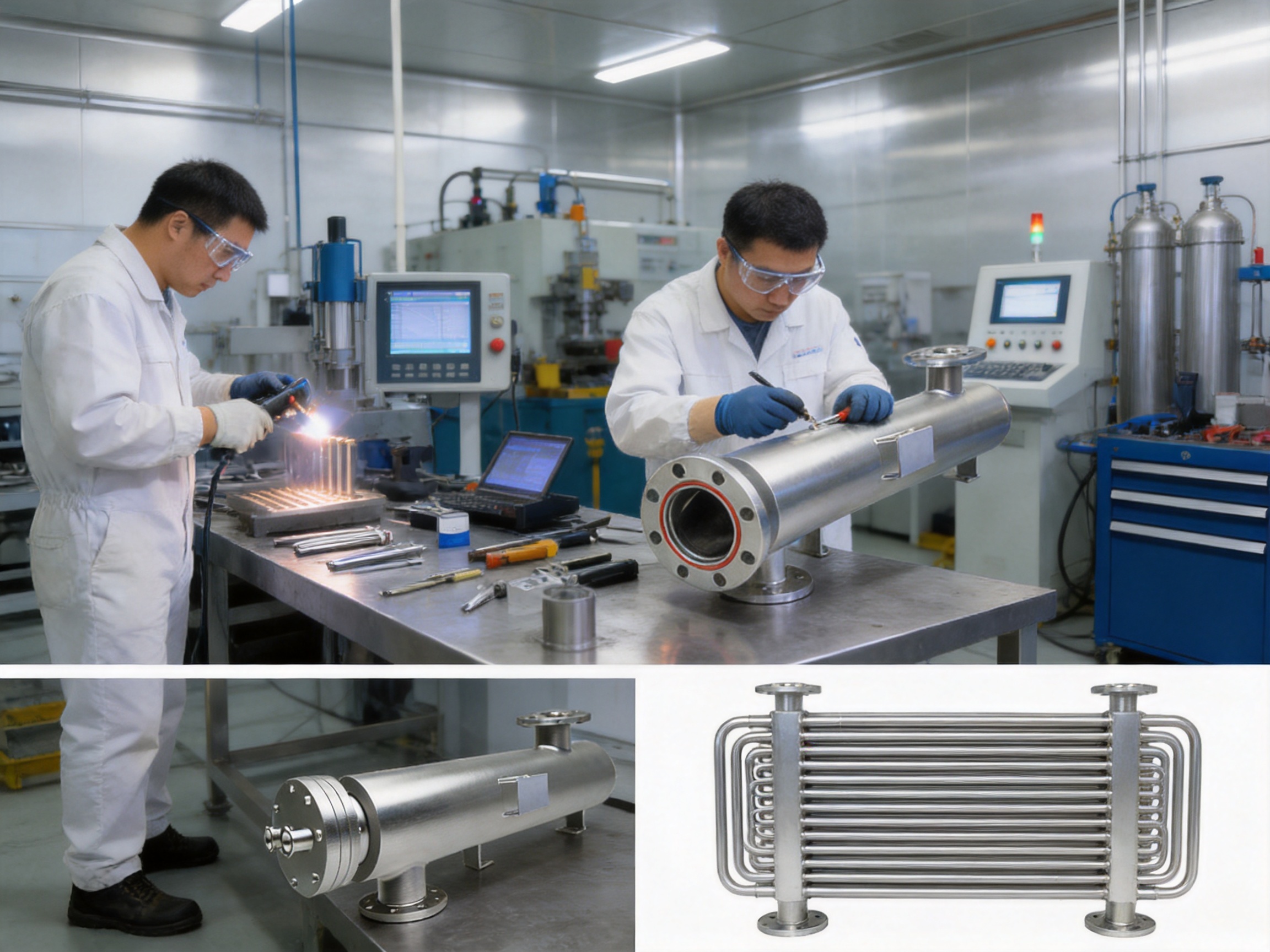
In food, beverage, biopharmaceutical, pharmaceutical, and other hygiene-sensitive industries, heat transfer equipment must do much more than transfer thermal energy. It must protect the product, support validated cleaning procedures, maintain reliable operation, and provide a clear means of detecting potential leakage before contamination becomes a serious process event.
The Sanitary DTS (Double Tube Sheet) Heat Exchanger is designed for precisely this type of demanding application. Its double-tube-sheet construction creates an additional protective barrier between the product and the utility medium. The arrangement is particularly valuable where the two fluids must remain completely separated, such as in injection water, purified water, process water, pharmaceutical liquids, food products, and other high-purity media.
Unlike conventional single-tube-sheet heat exchangers, a double-tube-sheet design provides dedicated leak detection points at the ends of the tube bundle. If a tube or tube-to-sheet connection develops a problem, leakage can be identified through the intermediate monitoring area before the two process streams mix directly. This design principle helps reduce cross-contamination risk and supports a more proactive approach to equipment safety.
The equipment combines sanitary construction, efficient heat transfer, drainability, flexible installation, customized engineering, and extensive inspection procedures. Manufactured with imported SUS316L stainless steel heat exchange tubes and designed according to recognized industry practices, it can be adapted to the process, pressure, temperature, space, and connection requirements of individual projects.
Why Hygienic Heat Transfer Requires More Than Conventional Equipment
Heat exchangers are often considered supporting equipment within a production line, but their performance can directly affect product quality, production continuity, energy consumption, and regulatory compliance. A failure in the heat transfer system may create temperature instability, incomplete sterilization, excessive energy use, or unplanned downtime.
In a conventional industrial process, a small internal leak may initially appear to be a maintenance issue. In a biopharmaceutical or food production environment, however, the consequences may be much more serious. A leak between a product stream and a cooling or heating medium can compromise a batch, interrupt production, trigger an investigation, and create extensive cleaning and validation requirements.
The risk becomes more significant when the utility side contains water, glycol, steam condensate, chemicals, or other fluids that are not permitted to enter the product stream. Similarly, valuable product must not migrate into the utility circuit. The heat exchanger therefore needs a structural method for separating the two fluids and identifying abnormal conditions as early as possible.
Sanitary equipment must also be designed to avoid stagnant areas, retain as little product as possible, and permit effective cleaning and drainage. Surfaces, welds, tube connections, bends, and internal transitions all require attention. A product that transfers heat efficiently but cannot be drained or inspected properly may still be unsuitable for a critical hygienic process.
The Sanitary DTS Heat Exchanger addresses these requirements through a combination of mechanical separation, sanitary materials, full-drain design, controlled fabrication, surface finishing, and systematic testing.
Double Tube Sheet Construction as a Safety Barrier
The defining feature of the equipment is its double-tube-sheet arrangement. The ends of the heat exchange tubes are secured by two separate tube sheets rather than by a single sheet alone. The space and connection arrangement between the tube sheets creates a monitoring zone that can serve as a leak detection point.
Under normal operating conditions, the product remains within the designated product-side tube bundle while the heating or cooling medium follows its own flow path. The double-tube-sheet structure keeps the two media physically separated at the tube ends, which are among the most important areas for monitoring during the service life of a heat exchanger.
If a tube wall, tube-to-sheet joint, or related sealing area experiences abnormal leakage, the intermediate zone can provide an opportunity for detection. This is fundamentally different from relying only on the final product analysis or on a pressure change that may occur after contamination has already taken place.
The design does not eliminate the need for proper operation, inspection, maintenance, and validation. Instead, it adds a robust passive safety feature that improves the ability to identify a developing problem. For industries where cross-contamination is unacceptable, this additional layer of protection can be more valuable than simply increasing heat transfer area.
Protection Against Cross-Contamination
Cross-contamination can occur when fluids on opposite sides of a heat exchanger communicate through a damaged tube or connection. In a single-tube-sheet construction, the location of the failure may be difficult to identify before the streams mix. A double-tube-sheet design separates the critical connection areas and creates a controlled route for inspection or leakage observation.
This arrangement is especially useful when the product side contains a high-value, sterile, or sensitive fluid and the service side contains a non-product utility. It can also be beneficial when both fluids must be protected from one another because of product loss, environmental concerns, or process integrity requirements.
Early Detection and Easier Maintenance
A leak detection point can support condition monitoring and reduce the time between the occurrence of a fault and its discovery. Earlier detection helps maintenance teams investigate the affected area, isolate the equipment, and determine whether the product or utility circuit requires additional testing.
By making the safety function visible and accessible, the double-tube-sheet concept can also support more organized maintenance planning. Instead of treating the heat exchanger as a sealed component with limited diagnostic capability, operators can incorporate leak monitoring into the equipment inspection procedure.
Sanitary Design for Product Protection and Full Drainability
Drainability is a basic but essential requirement for hygienic processing. Any liquid retained inside the equipment can create cleaning difficulties, encourage microbial growth, dilute the next batch, or complicate sterilization and validation. The Sanitary DTS Heat Exchanger is designed to support complete drainage through a sanitary side-drain arrangement and suitable orientation options.
The equipment can be installed vertically or horizontally according to the customer’s layout and process requirements. Orientation affects drainage, access, piping arrangement, and the position of vents and drains, so it should be considered during the engineering stage rather than after fabrication has been completed.
For water intake cooling applications involving injection water and purified water, the full-drain concept is particularly important. The design is intended to leave minimal residual liquid after the process has been emptied. This supports cleaning efficiency and helps reduce the risk of retained media between production campaigns.
Sanitary design also depends on the quality of internal surfaces. The product-contact surfaces can be mechanically polished or electropolished according to the project specification. The stated surface finish options include Ra values below 0.25 micrometers and other defined levels such as 0.4, 0.6, or 0.8 micrometers, depending on the selected configuration and application.
Smooth internal surfaces reduce the number of locations where particles, proteins, sugars, biological residues, or other process materials can adhere. They also support more repeatable cleaning results. Surface finish requirements should always be confirmed against the customer’s validation protocol, product characteristics, cleaning chemistry, and applicable regulatory expectations.
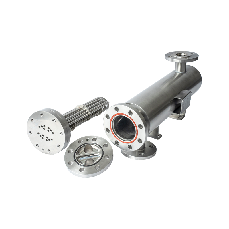
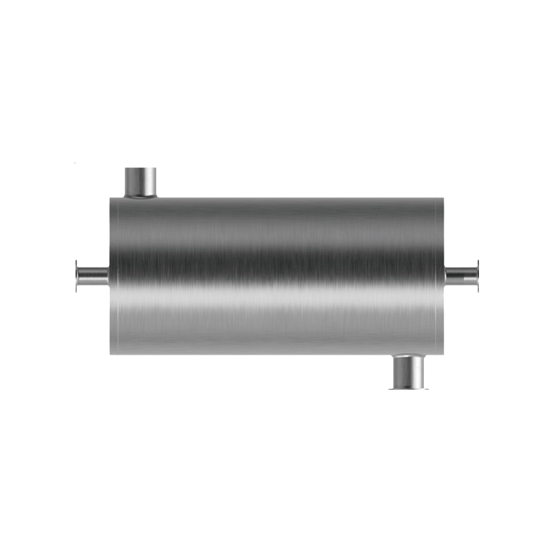
Sanitary DTS (Double Tube Sheet) Heat Exchanger
Flow Arrangement and Heat Transfer Performance
The Sanitary DTS Heat Exchanger is designed to provide effective thermal exchange while maintaining a clear separation between the product and utility circuits. In the described configuration, the product travels through the inner tube bundle while the cooling or heating medium moves in the opposite direction through the outer flow path. This counter-current arrangement can improve the temperature driving force across the exchanger.
Counter-current flow is widely used in heat exchanger design because it can achieve a favorable temperature profile along the length of the unit. The exact performance depends on the fluid properties, flow rates, inlet temperatures, outlet temperatures, allowable pressure drop, tube geometry, number of passes, and fouling characteristics.
Proper sizing is therefore more important than simply selecting a larger heat exchange area. Excessive area may increase the equipment footprint and cost, while insufficient area can prevent the process from reaching its required temperature. High flow velocity may improve heat transfer but can increase pressure drop and erosion risk. Low velocity may reduce pressure loss but can lower thermal performance and increase fouling potential.
The manufacturer uses selection software, engineering databases, and process calculations to match the exchanger with the customer’s operating conditions. Design margins are incorporated where appropriate to provide additional processing capacity and accommodate reasonable future changes in production demand.
Controlled Pressure Drop
Pressure drop is controlled according to the customer’s specified limits. This is important for pumps, flow-control valves, sterile filtration systems, and other upstream or downstream equipment. A heat exchanger that achieves high thermal duty at the cost of unacceptable pressure loss may create a larger problem in the complete process system.
The internal flow velocity is selected to balance heat transfer efficiency, pressure drop, cleaning performance, vibration, and mechanical service life. For multi-pass exchangers, the flow distribution between passes must also be evaluated to avoid unfavorable conditions that could reduce overall performance.
Transparent Heat Transfer Area Calculations
For U-tube configurations, the stated heat transfer area is calculated only from the straight tube sections. The U-bends are excluded from the heat transfer calculation. This approach provides a clear and conservative basis for comparing designs and allows customers to understand how the quoted heat transfer area has been determined.
Transparent calculations are valuable during technical review, procurement, validation, and future replacement planning. They reduce ambiguity between the customer’s process team and the equipment supplier, especially when multiple manufacturers use different methods for reporting heat transfer area.
Fouling Considerations
Fouling factors are applied in accordance with recognized heat exchanger design recommendations. Fouling can arise from suspended solids, mineral deposits, biological material, protein accumulation, thermal degradation, or chemical reactions at the heat transfer surface.
Although sanitary processes often include cleaning procedures designed to control deposits, fouling should still be considered in the design stage. A suitable fouling allowance helps maintain stable operation over the intended service interval and reduces the risk that heat transfer performance will decline rapidly after commissioning.
U-Tube Design and Mechanical Reliability
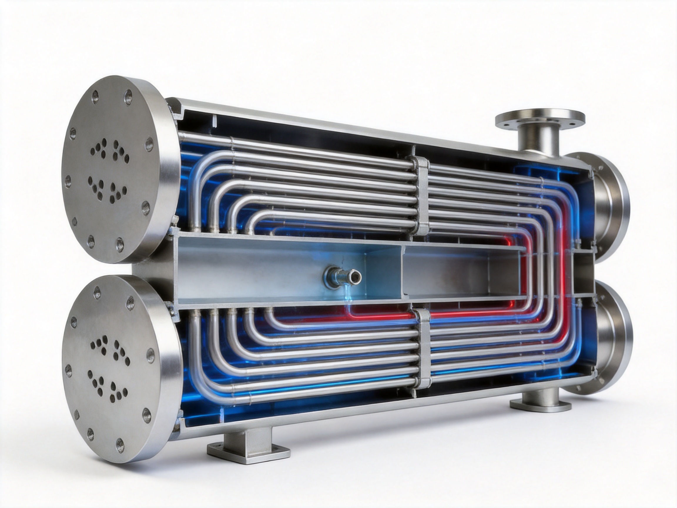
The equipment uses a U-tube design that is recommended in ASME-related engineering practice for suitable applications. In a U-tube exchanger, each tube returns through a curved section, allowing thermal expansion to be absorbed more naturally than in a completely fixed straight-tube arrangement.
This configuration can be advantageous when the shell side and tube side operate at different temperatures. The U-shape permits the tube bundle to accommodate thermal movement and reduces the need for an expansion joint. The expansion-joint-free structure removes a component that could otherwise become a source of fatigue, leakage, inspection difficulty, or maintenance demand.
U-tube design also allows a compact arrangement with a relatively efficient use of available length. However, the bend geometry must be controlled carefully. Poorly formed bends may reduce the internal flow area, create excessive stress, or complicate cleaning. For this reason, bend radii, tube contact, tube spacing, and fabrication quality are important parts of the manufacturing process.
The specified bend radii comply with ASME requirements, and the tube contact within the U-bends is controlled to achieve consistent geometry. The equipment can be customized with different tube diameters and bundle configurations according to the required duty and installation constraints.
Materials Selected for Hygienic Service
Heat exchange tubes are manufactured from imported SUS316L stainless steel according to the supplied specifications. SUS316L is commonly selected for hygienic and pharmaceutical applications because of its corrosion resistance, weldability, and suitability for contact with many process fluids and cleaning agents.
The low-carbon composition of 316L is beneficial for welded fabrication because it can reduce the risk of chromium carbide precipitation in appropriately controlled welding conditions. However, material selection must still consider the actual process media, chloride concentration, temperature, cleaning chemicals, sterilization cycles, and exposure duration.
The equipment specification also identifies 304, 316L, and KFM among available material options. The final selection should be confirmed through a technical review that includes product compatibility, utility conditions, surface finish requirements, pressure rating, regulatory expectations, and customer documentation requirements.
Tube outer diameter can be designed and manufactured according to user specifications. This flexibility allows the heat exchanger to be matched with the required flow velocity, heat transfer area, cleaning strategy, and space limitations. Connections may be configured with Tri-Clamp or flanged interfaces, depending on the process piping standard.
Surface Roughness and Sanitary Finish
The stated internal surface roughness for seamless electrode tubes ranges from approximately 0.3 to 0.6 micrometers, while sanitary-grade welded tube roughness does not exceed approximately 0.75 micrometers under the described specifications. Finished equipment can be supplied with a tighter specified surface requirement, including an Ra value below 0.25 micrometers where required.
Surface roughness is only one part of sanitary quality. The condition of welds, transitions, tube ends, drain points, internal corners, and polished areas must also be considered. A low roughness value cannot compensate for cracks, crevices, incomplete weld penetration, poor passivation, or inaccessible product-retention zones.
Advanced Manufacturing Processes
The performance of a sanitary heat exchanger depends heavily on manufacturing consistency. The design may be technically sound, but inaccurate tube positioning, uncontrolled expansion, poor welding, or inadequate polishing can compromise the final product.
Shiloc (Shanghai) Industrial Trading Co., Ltd. combines equipment manufacturing, engineering services, international trade, and process equipment supply. Its Shanghai facility covers approximately 3,000 square meters and includes capabilities for processing, welding, polishing, and quality control. The company reports a technical team of more than 20 specialists supporting project coordination and equipment delivery.
Hydraulic Expansion for Tube-to-Baffle Joining
An advanced hydraulic expansion process is used to join tubes and baffles. Compared with conventional roller expansion, hydraulic expansion can reduce localized surface damage and provide a more uniform connection along the required area.
Mechanical roller expansion may create concentrated deformation or surface marks if the process is not carefully controlled. Excessive expansion can thin the tube wall, create residual stress, or affect the tube’s long-term fatigue behavior. Hydraulic expansion applies pressure in a controlled manner and can support more consistent contact between the tube and baffle.
The use of monolithic bidirectional thin-wall tubes is intended to reduce stress concentration at the tube-to-baffle interface. This can improve consistency, reduce maintenance requirements, and contribute to a longer service life when combined with suitable design, fabrication, and operating conditions.
Welding and Seamless Joint Quality
Seamless joints are produced using imported equipment and controlled fabrication procedures. In sanitary equipment, welding quality affects not only pressure integrity but also cleanability and corrosion resistance. Welds must be properly formed, free from unacceptable defects, and finished in a manner consistent with the product-contact requirements.
Welding procedures should be selected according to the material grade, tube thickness, joint geometry, pressure conditions, and applicable quality system. The heat-affected zone, weld profile, internal penetration, and post-weld surface condition all require attention.
Shiloc’s manufacturing approach combines engineering review with processing, welding, polishing, and inspection capabilities. This integrated structure can reduce communication gaps between design and production and supports more direct control over customized equipment requirements.
Forged and Thickened Double-Plate Construction
The double-tube-sheet assembly uses a forged and thickened aseptic double-plate concept. The thicker construction improves mechanical strength and fatigue resistance at a critical part of the heat exchanger. It also supports the structural separation required for leak detection and cross-contamination protection.
Temperature cycling, pressure changes, vibration, and repeated cleaning procedures can impose stress on the tube sheet and tube connections. A robust plate design helps the equipment tolerate these conditions over a long operating period, provided that the exchanger is correctly installed and operated within its design limits.
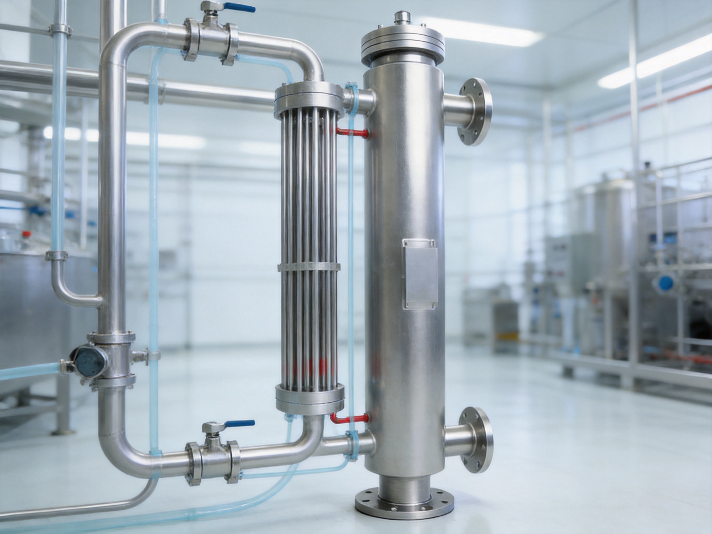
Engineering Analysis and Design Documentation
A reliable heat exchanger should be supported by more than a product drawing and a nominal heat transfer area. Customers in regulated or high-value industries often need technical evidence showing how the equipment was selected, how pressure boundaries were evaluated, and how vibration or resonance risks were addressed.
Each design report can include precise pressure points for the tube and shell walls based on customer-approved pressure locations. These pressure points help establish a clear engineering basis for the mechanical design and support review by the customer’s process, mechanical, and quality teams.
Pressure and Mechanical Analysis
The heat exchanger is designed for the specified operating and design pressure conditions. The reference specification identifies a design pressure of 10 bar and a design temperature of 143 degrees Celsius for the listed configuration. Actual project values should be confirmed during the quotation and engineering stages because the required pressure and temperature rating may vary by service.
Mechanical analysis should consider internal pressure, external pressure where applicable, thermal expansion, tube-sheet loading, nozzle loads, support reactions, transportation conditions, and pressure cycling. The use of a U-tube and expansion-joint-free arrangement can simplify some aspects of thermal movement, but it does not remove the need for a complete design review.
Vibration and Resonance Analysis
Flow-induced vibration can damage tubes, baffles, supports, and connections over time. It can also produce noise, fatigue, and unexpected maintenance problems. The stated engineering process includes 100 percent vibration and resonance analysis for the designed equipment.
For multi-pass heat exchangers, whether configured with straight tubes or U-tubes, counter-current and cross-flow conditions are analyzed. These evaluations help optimize the flow arrangement and identify potential areas of unfavorable turbulence, vibration, or uneven distribution.
Such analysis is especially important when the equipment operates with high flow rates, gas-liquid mixtures, pulsating pumps, large temperature differences, or low-viscosity fluids. The final design must balance thermal performance with mechanical stability.
Selection Software and Engineering Experience
Heat exchanger selection requires the interpretation of process data, not merely the entry of a few values into a standard catalog. Fluid viscosity may change significantly with temperature, while fouling behavior, allowable pressure drop, cleaning requirements, and startup conditions may influence the final design.
Shiloc applies specialized selection software, technical databases, and accumulated manufacturing experience to support product selection. This approach helps the design team compare alternative tube diameters, pass arrangements, heat transfer areas, materials, and installation orientations.
Professional design support is particularly important for customers purchasing customized equipment from overseas suppliers. Clear technical communication at the beginning of the project can prevent later difficulties involving connection sizes, support brackets, drainage, lifting, instrumentation, and documentation.
Testing and Inspection Before Shipment
Every sanitary heat exchanger should undergo systematic inspection before delivery. Testing verifies pressure integrity, construction quality, drainability, surface condition, cleanliness, and compliance with the agreed technical specification.
The described pre-shipment inspection program includes pressure testing, leakage-related examination, computerized performance verification, surface roughness measurement, visual inspection, endoscopic inspection, coding, and compliance checks.
Pressure Retention Testing
Hydrostatic testing is performed to verify that the equipment can withstand the specified fluid pressure without unacceptable leakage or deformation. The test pressure, holding time, test medium, and acceptance criteria should be defined in the inspection plan and agreed with the customer.
Pressure retention testing provides evidence of mechanical integrity before the equipment is connected to the production system. It does not replace correct installation or periodic inspection, but it is an essential part of factory acceptance.
Leakage and Internal Structure Examination
The supplied inspection description includes fuel permeation testing with X-ray analysis to check for leakage and internal structural issues. The exact test method should be clarified for each project because the appropriate non-destructive examination depends on the material, joint type, product application, and customer quality plan.
Additional inspection techniques may include visual examination, dye penetrant testing, radiographic examination, endoscopy, dimensional verification, weld inspection, and material traceability review. The selected methods should correspond to the criticality of the equipment and the requirements of the applicable standard.
Surface Roughness Measurement
A surface profilometer is used to verify the roughness of polished and electropolished surfaces. The stated acceptance target for selected surfaces is below 0.25 micrometers Ra. Measurement locations should be defined in advance, particularly around welds, tube ends, bends, drain points, and other areas that may be difficult to access.
Surface inspection supports both hygienic performance and documentation. For regulated manufacturing, measurement records can become part of the equipment qualification package and may be reviewed during commissioning or audit activities.
Visual and Endoscopic Inspection
Visual inspection verifies external condition, labeling, weld appearance, connection quality, support brackets, lifting points, and general workmanship. Endoscopic inspection allows the internal surfaces and tube paths to be examined where direct visual access is limited.
Before packing, an internal blowout inspection is performed to help ensure that the equipment is free from debris, metal particles, polishing residue, packaging material, or other foreign matter. This is especially important for sanitary equipment because contamination introduced before installation may be difficult to identify later.
Drainability and Functional Verification
A drainability test checks whether the internal medium can be completely removed through the designated drain arrangement. The result depends on the equipment orientation, piping configuration, drain location, internal geometry, and installation level.
Computer functionality verification may be included where the equipment is supplied with monitoring or control-related functions. The scope of the verification should be established according to the actual automation package and the customer’s commissioning requirements.
Standards and Compliance Considerations
The Sanitary DTS Heat Exchanger is designed with reference to recognized industry standards and customer-specific specifications. The described compliance framework includes ASME BPE-2005, ASME pressure equipment requirements, TEMA recommendations, Canadian Registration Number requirements, and CE/PED requirements where applicable.
ASME BPE provides principles relevant to bioprocess equipment, including hygienic design, materials, surface finish, fabrication, and documentation. TEMA recommendations provide a recognized basis for heat exchanger construction and performance considerations. CE/PED requirements may apply when equipment is supplied for the European market, while CRN registration may be necessary for particular Canadian jurisdictions.
Compliance is not automatically guaranteed by using a particular material or structural configuration. It depends on the final design, calculation package, fabrication procedures, inspection records, pressure category, documentation, and the regulatory requirements of the destination country.
For international projects, the technical contract should clearly define the applicable standards, nameplate requirements, material certificates, welding documentation, pressure test records, surface finish reports, inspection plans, certificates of conformity, and any registration responsibilities.
Typical Technical Parameters
The following table summarizes reference parameters for the described Sanitary DTS Heat Exchanger range. These values are examples for preliminary selection and should not replace a project-specific engineering review.
| Parameter | Reference Value or Option | Engineering Note |
|---|---|---|
| Heat transfer area | 1–20 m² | Final area depends on duty, flow, temperature approach, and fouling allowance. |
| Design temperature | 143°C | Confirm according to process, sterilization, and utility conditions. |
| Design pressure | 10 bar | Actual pressure rating must be confirmed for each side of the exchanger. |
| Material options | 304, 316L, KFM | 316L is commonly selected for sanitary product-contact service. |
| Tube material | Imported SUS316L stainless steel | Tube diameter and construction can be customized. |
| Connections | Tri-Clamp or flange | Connection type should match the site piping standard. |
| Surface finish | Ra below 0.25, 0.4, 0.6, or 0.8 μm | Final value depends on the customer’s hygiene and validation requirements. |
| Installation | Vertical or horizontal | Orientation should support drainability, access, and piping layout. |
| Tube configuration | U-tube | U-bends are excluded from the stated heat transfer area calculation. |
| Leak protection | Double tube sheet with leak detection points | Provides an additional barrier between product and utility media. |
Reference Models and Dimensional Flexibility
The available reference models demonstrate how the number of U-tubes, shell diameter, length, and weight can vary according to the required capacity and layout. The model range supports preliminary space planning, but the final dimensions should be confirmed after the heat duty, connection orientation, support arrangement, and maintenance access have been reviewed.
| Model | Number of U-Tubes | U-Tube Diameter | Shell Diameter | Total Length | Reference Weight |
|---|---|---|---|---|---|
| HY-SD-09065 | 9 | 10 mm | 90 mm | 1,050 mm | 56 kg |
| HY-SD-11065 | 11 | 10 mm | 102 mm | 1,050 mm | 75 kg |
| HY-SD-19150 | 19 | 10 mm | 116 mm | 1,900 mm | 90 kg |
| HY-SD-21150 | 21 | 10 mm | 140 mm | 1,900 mm | 115 kg |
The dimensional range illustrates the importance of early coordination between the heat exchanger supplier and the installation contractor. Space must be reserved not only for the shell but also for tube-side connections, drain points, vents, lifting, inspection, removal, and potential maintenance activities.
Advantages Over Conventional Single Tube Sheet Heat Exchangers
The principal advantage of the Sanitary DTS design is its additional separation barrier. A conventional single-tube-sheet exchanger may be appropriate for many industrial applications, but it provides less structural redundancy in situations where cross-contamination cannot be tolerated.
The DTS configuration provides dedicated leak detection points and makes the tube-end connection zone more suitable for monitoring. This is a significant advantage for biopharmaceutical, food, beverage, and purified-water applications.
The full-drain design is another important distinction. Equipment designed for general industrial service may retain liquid in low points, dead legs, or poorly oriented channels. The sanitary DTS configuration is developed with drainage and cleaning requirements in mind, supporting residue reduction and more repeatable hygienic operation.
The use of imported 316L tubes, sanitary surface finishing, U-tube construction, hydraulic expansion, and forged double plates further distinguishes the equipment from low-cost units that prioritize initial price over lifecycle reliability.
Expansion-joint-free construction can reduce the number of components requiring inspection and lower the potential for joint-related failures. The U-tube arrangement accommodates thermal movement while supporting a compact design.
Finally, the equipment is not limited to a single standardized model. Tube diameter, heat transfer area, material, installation direction, connection type, pressure rating, and other design details can be adapted to the customer’s actual process.
Customization for Different Process Requirements
Different industries and production lines require different heat exchanger configurations. A purified water cooling application may have very different requirements from a viscous food product, a fermentation broth, a pharmaceutical intermediate, or a high-temperature cleaning circuit.
Customization begins with a review of the process data. Important information includes the fluid name, composition, flow rate, inlet and outlet temperatures, operating pressure, design pressure, viscosity, density, specific heat, allowable pressure drop, cleaning method, sterilization conditions, and required production capacity.
The installation environment must also be considered. Available space, floor loading, support locations, connection direction, access for inspection, lifting limitations, ambient temperature, and drainage arrangements can influence the final design.
For overseas projects, documentation and certification requirements should be identified at the beginning. A customer may require material certificates, welding procedure specifications, welder qualifications, surface finish records, pressure test reports, dimensional drawings, calculation reports, inspection plans, or regulatory registration documents.
Shiloc provides engineering coordination and international trade support in addition to equipment supply. This can help customers manage technical communication, manufacturing schedules, quality coordination, export procedures, and project documentation through one supplier interface.
Applications in Food, Beverage, and Biopharmaceutical Manufacturing
The Sanitary DTS Heat Exchanger is suitable for process environments where product safety, fluid separation, and cleanability are central requirements.
Injection Water and Purified Water Systems
Injection water and purified water systems require careful temperature control and hygienic design. The exchanger can be used as a water intake cooler or as part of a controlled water preparation and distribution system, subject to the specific validation and regulatory requirements of the project.
The drainable construction, 316L tube material, smooth internal surfaces, and double-tube-sheet protection are relevant to these applications. The final design must be integrated with the water system’s circulation, sanitization, monitoring, and qualification strategy.
Biopharmaceutical Processing
Biopharmaceutical processes may involve expensive products, sterile or low-bioburden conditions, and strict separation between product and utility media. A DTS exchanger can be applied to heating or cooling duties where early leak detection and product protection are priorities.
Potential uses may include temperature adjustment of process liquids, controlled cooling before filtration or filling, utility-side temperature management, and other duties that require sanitary heat transfer. The actual application depends on the process development package and validation plan.
Food and Beverage Production
Food and beverage products often contain sugars, proteins, fats, suspended particles, or other components that can foul heat transfer surfaces. A properly selected exchanger can provide the required thermal duty while supporting cleaning and drainage.
Applications may include product cooling, water cooling, ingredient temperature control, and process utility duties. The correct surface finish, tube diameter, flow velocity, and clean-in-place procedure should be selected according to the product characteristics.
Daily Chemical and Fine Chemical Processes
Daily chemical and fine chemical products may also require cleanable, corrosion-resistant, and tightly controlled heat transfer equipment. In these applications, material compatibility and cleaning chemistry are particularly important. The DTS design can provide an additional separation barrier where product value or contamination sensitivity justifies the investment.
Company Manufacturing and Supply Chain Strengths
Shiloc (Shanghai) Industrial Trading Co., Ltd. was established in March 2026 in Fengxian District, Shanghai. The company specializes in the import and export of goods and technology, import and export agency services, equipment manufacturing, and engineering and technical services.
Its product and service focus includes fluid equipment and process systems for food and beverage, biopharmaceutical, daily chemical, and fine chemical industries. The company’s portfolio includes heat exchangers, aseptic mixing equipment, and related process equipment.
The company states that its equipment development is built on European know-how and Danish design principles. Its Shanghai facility provides approximately 3,000 square meters of space for processing, welding, polishing, and quality control, supported by more than 20 technical specialists.
This combination of manufacturing and international trade capabilities can be useful for global customers who need more than a standard catalog product. Equipment procurement often involves technical clarification, drawing approval, inspection coordination, export documentation, logistics, and installation support. A supplier with capabilities across these stages can reduce communication gaps and simplify project management.
Shiloc emphasizes innovative design, process optimization, safe and efficient equipment, reliable supply, traceability, and personalized customer service. These priorities are particularly relevant to sanitary equipment because every project may require a different combination of materials, dimensions, surface finish, connections, documentation, and inspection.
For customers comparing suppliers, the most important evaluation should include manufacturing transparency, engineering responsiveness, quality records, inspection capability, material traceability, customization experience, and after-sales support. A competitive purchase price is valuable, but it should be assessed together with the equipment’s lifecycle performance and the potential cost of contamination, downtime, and replacement.
Installation, Commissioning, and Operation
Correct installation is essential to achieving the intended performance of the Sanitary DTS Heat Exchanger. The unit should be positioned to support the required flow direction, drainage, venting, inspection access, and maintenance procedures.
Factory-welded lifting and mounting brackets can simplify handling and installation. Nevertheless, lifting equipment must be selected according to the actual shipping weight, center of gravity, and site conditions. Supports should be designed to prevent excessive nozzle loads or distortion of the exchanger.
Piping should be cleaned before connection. Foreign particles, welding slag, and construction debris can damage valves, contaminate the product system, or obstruct small passages. Temporary strainers and flushing procedures may be used during commissioning according to the project method statement.
During startup, operators should gradually introduce the process and utility fluids. Sudden pressure changes or rapid temperature changes can create thermal shock and mechanical stress. Flow rates should be increased in a controlled manner while monitoring pressure, temperature, leakage points, and drain behavior.
Operating conditions should remain within the approved design limits. Excessive pressure, unexpected vacuum, severe temperature cycling, inadequate flow, or incompatible cleaning chemicals may shorten equipment life. Preventive maintenance should include inspection of connections, leak detection areas, surface condition, pressure performance, and drainability.
Lifecycle Value and Total Cost of Ownership
The purchase price of a heat exchanger represents only one part of its total cost. A lower-cost unit may become expensive if it causes repeated contamination events, difficult cleaning, frequent repairs, high pressure drop, unstable heat transfer, or long replacement lead times.
The DTS design can reduce lifecycle risk by improving separation between product and utility media. The expansion-joint-free construction can reduce the number of potential failure points. Hydraulic expansion and controlled tube fabrication support durable tube-to-baffle connections. Full drainability and smooth surfaces can make cleaning and inspection more predictable.
Energy efficiency also affects operating cost. By optimizing flow velocity, heat transfer area, counter-current flow, and pressure drop, the exchanger can help reduce the utility demand associated with heating and cooling. The exact energy performance depends on the process conditions and the efficiency of the complete thermal system.
Customization can provide additional value when it prevents the customer from having to modify an existing production line. A heat exchanger designed for the available space and connection layout may reduce installation work, piping changes, and commissioning time.
Selection Checklist for Buyers
Before ordering a sanitary double-tube-sheet heat exchanger, buyers should prepare a complete technical data sheet. The following information is particularly useful:
Product and utility fluid names should be identified, including composition, concentration, viscosity, density, corrosive properties, and whether the fluids are sterile, purified, flammable, or hazardous.
Required inlet and outlet temperatures should be provided for both sides. Flow rates, operating pressures, design pressures, allowable pressure drops, and expected operating hours should also be specified.
Cleaning and sterilization requirements should include cleaning chemicals, temperature, pressure, cycle frequency, flow velocity, sterilization method, and any restrictions on materials or surface finish.
The customer should define the desired heat transfer area, installation direction, available space, pipe connection standards, support requirements, lifting limitations, insulation requirements, instrumentation, and drain locations.
Documentation requirements should be agreed before manufacturing begins. These may include drawings, calculation reports, material certificates, weld records, inspection reports, pressure test certificates, surface roughness results, endoscopic records, certificates of conformity, and export documents.
Frequently Asked Questions
Q1: What is a Sanitary DTS Heat Exchanger?
A Sanitary DTS Heat Exchanger is a hygienic heat transfer unit that uses a double-tube-sheet structure to separate the product and utility media. The tube-sheet arrangement creates additional protection against cross-contamination and provides designated areas for leak detection.
Q2: Why is a double tube sheet safer than a single tube sheet?
A double tube sheet adds an extra physical barrier at the tube ends, which are critical connection areas. If a tube or connection develops a leak, the intermediate monitoring area can help identify the problem before direct mixing of the product and utility fluids occurs.
Q3: Can the equipment be installed horizontally?
Yes. The unit can be installed vertically or horizontally according to the customer’s available space and process requirements. The selected orientation must support proper drainage, venting, piping, inspection, and maintenance access.
Q4: Is the heat exchanger suitable for purified water systems?
The design is intended for applications such as injection water and purified water cooling systems, subject to project-specific qualification and regulatory requirements. Material, surface finish, drainability, connection design, cleaning, and validation requirements should be confirmed before ordering.
Q5: What material is used for the heat exchange tubes?
The heat exchange tubes are made from imported SUS316L stainless steel under the described specification. Other material options, including 304, 316L, and KFM, may be available depending on the project requirements and compatibility review.
Q6: Can tube diameter and heat transfer area be customized?
Yes. Tube diameter, heat transfer area, tube quantity, shell dimensions, pressure rating, connection type, surface finish, and installation arrangement can be adjusted according to the process and site conditions.
Q7: Are the U-bends included in the heat transfer area?
No. The stated calculation method includes only the straight tube sections and excludes the U-bends. This provides a clear and conservative basis for reporting the effective heat transfer area.
Q8: What inspections are performed before shipment?
Pre-shipment inspections can include hydrostatic pressure testing, leakage-related examination, performance verification, surface roughness measurement, visual inspection, endoscopic inspection, drainability testing, internal blowout inspection, coding, and compliance checks.
Q9: What surface finish is available?
The reference specifications include surface finish levels below 0.25, 0.4, 0.6, and 0.8 micrometers Ra. The required finish should be selected according to the product, cleaning system, validation plan, and applicable sanitary standard.
Q10: How does the U-tube design improve reliability?
The U-tube arrangement allows thermal expansion to be accommodated naturally and can reduce the need for an expansion joint. This may lower the number of components exposed to fatigue or leakage while supporting a compact heat exchanger structure.
Q11: What information is needed for a quotation?
The supplier generally needs the fluid properties, flow rates, inlet and outlet temperatures, operating and design pressures, allowable pressure drops, cleaning requirements, material preferences, surface finish, connection standards, installation orientation, available space, and documentation requirements.
Q12: Does the manufacturer support international projects?
Shiloc provides international trade, import and export agency, equipment manufacturing, engineering, and technical services. Its supply chain support is intended to assist customers with technical communication, quality coordination, documentation, logistics, and project delivery.
Conclusion
The Sanitary DTS Heat Exchanger is designed for applications where thermal performance and hygienic safety must work together. Its double-tube-sheet construction provides an additional separation barrier and dedicated leak detection points, helping protect product integrity and reduce the risk of cross-contamination.
Its full-drain design, sanitary surface options, SUS316L heat exchange tubes, U-tube configuration, expansion-joint-free structure, hydraulic expansion process, and forged double-plate construction support reliable operation in demanding food, beverage, biopharmaceutical, pharmaceutical, purified-water, and fine chemical environments.
The equipment also benefits from detailed engineering analysis, pressure and vibration evaluation, transparent heat transfer calculations, customized dimensions, flexible installation, and extensive pre-shipment inspection. These features make it more than a standard heat exchanger: it is a process safety component designed to support quality, compliance, and production continuity.
For customers evaluating suppliers, the strongest solution is not necessarily the unit with the lowest initial cost. The better choice is the heat exchanger that matches the process accurately, provides clear documentation, supports sanitary operation, allows effective maintenance, and protects the production system throughout its service life.
With manufacturing, engineering, polishing, welding, quality control, and international trade capabilities, Shiloc (Shanghai) Industrial Trading Co., Ltd. provides customized Sanitary DTS Heat Exchanger solutions for global process equipment users. Its focus on technical coordination, traceability, and customer-specific design makes the equipment suitable for companies upgrading production lines or developing new hygienic processing systems.
References
1. American Society of Mechanical Engineers. ASME BPE: Bioprocessing Equipment Standard.
2. American Society of Mechanical Engineers. ASME Boiler and Pressure Vessel Code, Section VIII, Pressure Vessels.
3. Tubular Exchanger Manufacturers Association. Standards of the Tubular Exchanger Manufacturers Association.
4. European Union. Pressure Equipment Directive requirements for applicable pressure equipment.
5. Canadian Registration Number requirements for applicable pressure vessels and process equipment.
6. Good Manufacturing Practice principles for pharmaceutical and biopharmaceutical production.
7. Food and Drug Administration. Current Good Manufacturing Practice requirements for applicable food and pharmaceutical processes.
8. Hygienic design principles for stainless steel process equipment, welded assemblies, surface finishes, drainage, and cleanability.
9. Manufacturer-provided technical specifications for Sanitary DTS Double Tube Sheet Heat Exchangers.
10. Manufacturer-provided inspection, testing, material, dimensional, and customization information.
Product: Sanitary DTS (Double Tube Sheet) Heat Exchanger
PREV:Bottom-Entry High-Shear Magnetic Emulsifier for Hygienic Food and Biopharmaceutical Processing
NEXT:Plate Pasteurizer Complete Skid: Efficient Thermal Processing for Food and Biopharmaceutical Production
NEXT:Plate Pasteurizer Complete Skid: Efficient Thermal Processing for Food and Biopharmaceutical Production
Interested in cooperation or have questions?
Recommended LINS
✦
Food Processing Skid System
Food and Beverage Process System
Aseptic Processing Equipment for Liquid Foods
Sanitary Process Skid
CIP Skid System for Food Industry
Milk Processing Heat Exchanger
UHT Processing Equipment for Plant Based Milk
UHT Processing System for Dairy Products
Plate Heat Exchanger Pasteurization System
Industrial Liquid Food Sterilization Equipment
Let'S Work Together Welcome Aboard!
-

haikexin@haikexin.com
+8613391278930
-
 +86-21-57560276
-
 No. 2819, Sihu Road,Fengxian District, Shanghai, China
Join Our Mailing List
Copyright © Shiloc (Shanghai) Industrial Trading Co., Ltd. All Rights Reserved.
Process Systems & Equipment For Food & Biopharma Manufacturers
