
 English
 русский
 Português
 Français

 Read More

Product Category
NEW Category
Contact us
Contact Us
We specialise in the research, development and manufacture of electrical wires and cables.
 +86-21-57560276
Sanitary DTS Heat Exchangers for Safer Food and Biopharmaceutical Processing
Content
- 1 What Is a Sanitary DTS Heat Exchanger?
- 2 Why Double Tube Sheets Matter in Hygienic Processing
- 3 Sanitary Design Features for Food and Biopharmaceutical Applications
- 4 Thermal Design and Energy Performance
- 5 U-Tube Construction and Mechanical Reliability
- 6 Advanced Tube-to-Baffle Joining Process
- 7 Manufacturing Strengths Behind the Equipment
- 8 Quality Control, Testing, and Documentation
- 9 Compliance with Recognized Standards
- 10 Reference Models and Dimensional Options
- 11 Advantages Compared with Conventional Heat Exchangers
- 12 Customization for Different Process Requirements
- 13 Applications in Food, Beverage, and Biopharmaceutical Production
- 14 How to Select the Correct Sanitary DTS Heat Exchanger
- 15 Vibration, Resonance, and Mechanical Analysis
- 16 Installation, Commissioning, and Maintenance Considerations
- 17 Why Supplier Capability Matters
- 18 Economic Value and Lifecycle Benefits
- 19 Frequently Asked Questions
- 19.1 Q1: What is the main purpose of a double tube sheet?
- 19.2 Q2: Is a sanitary DTS heat exchanger suitable for purified water and injection water systems?
- 19.3 Q3: Can the unit be installed horizontally?
- 19.4 Q4: What materials are available?
- 19.5 Q5: What surface roughness can be provided?
- 19.6 Q6: Does the heat transfer area include the U-bends?
- 19.7 Q7: Why is the U-tube design useful?
- 19.8 Q8: How is the tube-to-baffle connection made?
- 19.9 Q9: Can the tube diameter and heat transfer area be customized?
- 19.10 Q10: What tests are performed before shipment?
- 19.11 Q11: Which standards may apply?
- 19.12 Q12: What information is needed for a quotation?
- 19.13 Q13: How does the supplier support overseas projects?
- 20 Conclusion
- 21 References
- 22 Product: Sanitary DTS (Double Tube Sheet) Heat Exchanger
Heat transfer is an essential operation in food, beverage, pharmaceutical, biopharmaceutical, daily chemical, and fine chemical manufacturing. Water, product fluids, cleaning solutions, process media, and utility fluids must often be heated or cooled within tightly controlled temperature ranges. At the same time, the equipment must protect the product from contamination, support effective cleaning, drain completely, and remain reliable during continuous operation.
For many applications, a conventional shell-and-tube heat exchanger can provide adequate thermal performance. However, ordinary designs may not provide the level of separation, leak detection, drainability, surface quality, and documentation required for sensitive production processes. In these environments, equipment selection is not determined by heat transfer area alone. The design must also address cross-contamination risk, hygienic construction, material compatibility, fatigue resistance, inspection, validation, and long-term maintainability.
A sanitary DTS, or double tube sheet, heat exchanger is designed to respond to these requirements. Its two-tube-sheet construction creates an additional separation barrier between the product side and the utility side. The space between the tube sheets can serve as a leak detection zone, allowing a potential tube or joint failure to be identified before the two process fluids directly mix. Combined with stainless steel construction, a drainable configuration, controlled surface finishing, and customizable process connections, the DTS design is particularly suitable for high-hygiene production systems.
This article examines the working concept, sanitary advantages, manufacturing processes, technical characteristics, inspection procedures, customization options, and application value of sanitary DTS heat exchangers. It also explains why an experienced process equipment supplier with engineering, fabrication, quality control, and international trade capabilities can provide greater value than a supplier offering only a standard catalog unit.
What Is a Sanitary DTS Heat Exchanger?
A sanitary DTS heat exchanger is a hygienic heat transfer unit that uses two tube sheets at the ends of the heat exchange tube bundle. The tube sheets are arranged so that the product circuit and the service-fluid circuit remain separated by an intermediate space. This configuration differs from a conventional single-tube-sheet heat exchanger, in which a tube-to-tube-sheet joint is the primary separation point between the two media.
In a typical sanitary DTS arrangement, the product flows through the inner tube bundle while the cooling or heating medium flows through the surrounding shell-side or outer tube passage. Depending on the process design, the two streams may be arranged in counter-current or cross-flow patterns to improve thermal efficiency. The two ends of the tube bundle are secured by forged, thickened, aseptic double plates. These plates create a safety barrier and provide points for monitoring or detecting leakage.
The double tube sheet is not simply an additional structural component. It is a risk-control feature. If a tube develops a leak, the intermediate space can provide an indication before product and utility fluid become directly interconnected. The exact detection method depends on the design and project requirements. It may include visual observation, drainage, pressure monitoring, conductivity monitoring, or another validated approach selected by the user.
Sanitary DTS heat exchangers are commonly used for injection water cooling, purified water systems, product cooling, process water temperature control, and other applications in which accidental media mixing is unacceptable or difficult to tolerate. They may be installed vertically or horizontally, subject to the process layout, drainage requirements, maintenance access, and available space.
Why Double Tube Sheets Matter in Hygienic Processing
In food and biopharmaceutical manufacturing, contamination can have consequences far beyond the cost of replacing a damaged component. A contamination event may require product disposal, line cleaning, investigation, revalidation, production interruption, and regulatory review. The design of the heat exchanger therefore needs to reduce the probability and impact of an internal failure.
A single tube sheet provides a reliable connection when properly designed and manufactured. Nevertheless, it normally does not provide the same level of physical separation and monitoring capability as a double tube sheet arrangement. In a DTS unit, the intermediate space helps isolate the two media and makes it possible to identify leakage at the tube ends. This is particularly valuable where the product side contains a high-value, sterile, or sensitive fluid and the utility side contains water, steam, glycol, or another medium that must not enter the product stream.
The DTS concept provides several practical benefits:
First, it creates an additional barrier against cross-contamination. Product and utility media do not rely on one single tube-sheet region for separation.
Second, it supports early detection of abnormal conditions. Leakage can be identified at a designated detection point before the problem develops into direct bidirectional mixing.
Third, it improves the manageability of quality investigations. A defined leak detection zone can help maintenance and validation personnel understand where a failure may have occurred.
Fourth, it supports risk-based equipment design. Instead of treating a heat exchanger as a simple thermal device, the DTS structure integrates safety, monitoring, and hygienic requirements into the equipment architecture.
These advantages make the design more appropriate than a basic single-tube-sheet exchanger for high-risk applications. The precise level of protection still depends on correct engineering, material selection, welding quality, testing, installation, and operating procedures. A double tube sheet is a major design advantage, but it must be supported by disciplined manufacturing and inspection.
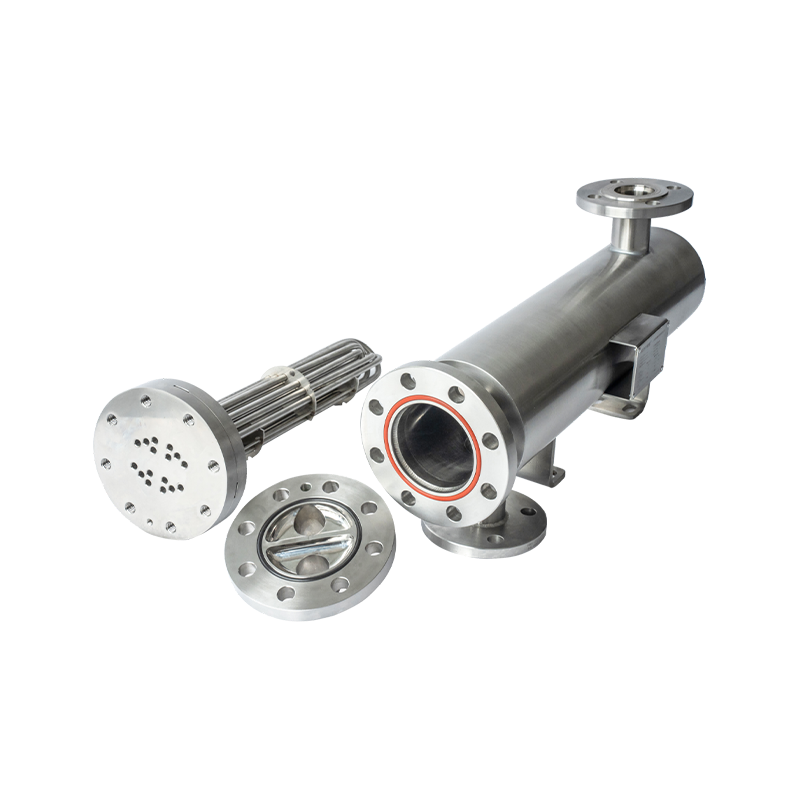
Sanitary DTS (Double Tube Sheet) Heat Exchanger
Sanitary Design Features for Food and Biopharmaceutical Applications
Full Drainability and Side-Drain Configuration
Complete drainage is fundamental to hygienic process equipment. Residual liquid trapped inside a heat exchanger can support microbial growth, create a contamination risk, complicate cleaning, and increase the time needed to prepare the system for the next batch or campaign.
The sanitary DTS heat exchanger is designed with drainage in mind. A side-drain arrangement helps the process medium leave the equipment rather than remain in low points or dead zones. The final drainage performance depends on installation orientation, piping slope, connection arrangement, internal geometry, and the specific process fluid. For this reason, the equipment should be integrated with a properly designed hygienic piping system rather than treated as an isolated component.
For injection water and purified water systems, full-drain design is especially important. The equipment can be configured to support cleaning, rinsing, sanitization, and inspection procedures. Drainability testing before shipment provides an additional verification that the internal arrangement can achieve the intended process requirement.
Hygienic Materials
Imported SUS316L stainless steel heat exchange tubes are used for applications requiring corrosion resistance and compatibility with hygienic processes. Stainless steel 316L is widely selected for biopharmaceutical and food processing equipment because of its low carbon content, corrosion resistance, cleanability, and suitability for controlled welding and polishing procedures.
Depending on the project, other material options may be considered, including 304 stainless steel or KFM-related material configurations identified in the technical specification. The final selection should be based on the process fluid, temperature, pressure, cleaning chemistry, chloride exposure, sterilization conditions, and applicable customer standards.
Material selection is not limited to the tubes. Tube sheets, shells, nozzles, fittings, supports, weld filler materials, gaskets, and instrumentation interfaces must also be reviewed. A technically suitable tube combined with an unsuitable gasket or poorly finished connection can compromise the sanitary performance of the complete assembly.
Controlled Surface Finish
Surface roughness affects cleanability. A smoother surface generally reduces the opportunity for product residues and microorganisms to remain attached, although surface finish alone cannot replace an effective cleaning and sanitization procedure.
The specified internal surface finish can be selected according to the application. The reference specification lists surface roughness values such as Ra below 0.25 micrometers and other options including approximately 0.4, 0.6, and 0.8 micrometers. For seamless electrode tubes, the stated inner surface roughness range is approximately 0.3 to 0.6 micrometers. For sanitary welded tubes, the roughness does not exceed approximately 0.75 micrometers under the referenced configuration.
Mechanically polished and electropolished surfaces should be inspected using appropriate measurement instruments. A surface profilometer can verify the Ra value, while visual inspection, endoscopic inspection, and surface photometer testing can provide additional evidence of surface condition and consistency.
Sanitary Connections and Installation Flexibility
The unit can be equipped with Tri-Clamp or flanged connections according to the process design. Tri-Clamp connections are widely used in hygienic piping because they can be disassembled efficiently and are available in standardized sanitary configurations. Flanged connections may be selected where higher mechanical strength, larger pipe sizes, or compatibility with an existing plant standard is required.
The heat exchanger can be designed for vertical or horizontal installation. Vertical installation may simplify natural drainage in certain layouts, while horizontal installation can help accommodate restricted headroom or specific skid arrangements. Pre-welded lifting and mounting brackets can simplify handling and installation at the customer’s site.
Thermal Design and Energy Performance
A sanitary heat exchanger must provide more than hygienic separation. It must transfer the required heat while maintaining an acceptable pressure drop, flow velocity, residence time, and operating margin. Poor thermal design can cause excessive pumping energy, unstable process temperatures, insufficient capacity, or accelerated fouling.
The engineering approach for the DTS unit combines heat transfer calculations, hydraulic analysis, material selection, vibration review, and mechanical design. Internal flow velocity is optimized to support efficient heat transfer while keeping the pressure drop within the limits specified by the customer. A reasonable design margin can also be incorporated to accommodate future increases in production capacity or moderate changes in process conditions.
The product side and utility side can be arranged for counter-current flow, which generally provides a stronger temperature-driving force than parallel flow under comparable conditions. Multi-pass designs may use a combination of counter-current and cross-flow analysis. The actual flow pattern must be evaluated for the selected number of passes, tube arrangement, baffle configuration, fluid properties, and operating range.
Design calculations include fouling factors in accordance with applicable heat exchanger design recommendations. Fouling factors help account for the expected reduction in thermal performance caused by deposits over time. The selected value should reflect the actual fluid, cleaning regime, operating temperature, and production conditions. Excessive fouling allowances can lead to an unnecessarily large unit, while insufficient allowances can result in inadequate capacity after a period of operation.
Heat transfer area is calculated based on the straight tube sections. The U-bends are excluded from the heat transfer area calculation. This approach provides a clear and transparent basis for comparing the stated heat transfer area with the actual effective transfer geometry. It also prevents the customer from receiving an inflated area figure based on sections that do not provide the same heat transfer contribution as the straight tube length.
The reference capacity range is approximately 1 to 20 square meters of heat transfer area, with the final area determined by the process duty and engineering calculation. The design temperature listed for the reference configuration is 143 degrees Celsius, and the design pressure is 10 bar. These values are reference parameters rather than universal operating limits. Every project should be confirmed against the final pressure-temperature envelope, fluid properties, sterilization conditions, and applicable code requirements.
| Parameter | Reference specification | Engineering consideration |
| Heat transfer area | Approximately 1–20 m² | Final area is selected according to duty, flow, temperature program, and fouling allowance |
| Design temperature | Up to approximately 143°C | To be confirmed against the pressure-temperature combination and process cycle |
| Design pressure | Approximately 10 bar | Final pressure rating depends on the complete equipment design and applicable code |
| Materials | 304, 316L, and project-specific options | Selection depends on product, cleaning chemicals, sterilization, and corrosion conditions |
| Vent connection | Tri-Clamp or flange | Configured to match hygienic piping and customer standards |
| Surface finish | Ra options below approximately 0.25–0.8 µm | Final finish is selected according to process hygiene and validation requirements |
U-Tube Construction and Mechanical Reliability
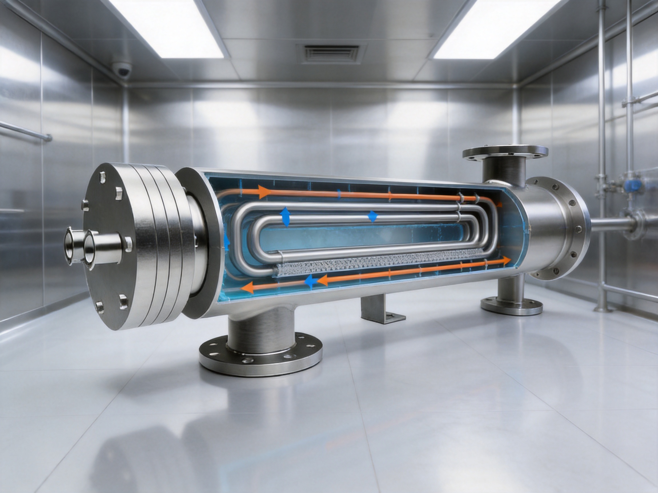
The U-tube configuration is recommended in the referenced design approach and is aligned with the structural principles commonly used in pressure equipment engineering. A U-tube can accommodate thermal expansion through its curved geometry, reducing the need for an external expansion joint.
The expansion joint-free design is one of the important advantages of this construction. Expansion joints can be effective when properly engineered, but they introduce additional components that may require inspection, maintenance, and specialized evaluation. By allowing thermal movement through the U-tube arrangement, the heat exchanger can reduce dependence on a separate expansion joint and potentially lower the risk of expansion-joint-related malfunction.
The U-bend geometry must be manufactured accurately. Bend radii should comply with applicable ASME requirements, and the contact condition within the bends must be controlled. Poor bending can cause thinning, wrinkling, flattening, excessive stress, or undesirable flow resistance. The use of appropriate equipment and process controls is therefore essential.
The reference design uses a forged, thickened, aseptic double-plate tube sheet. Forging can provide a dense and mechanically robust material structure, while the increased thickness improves resistance to pressure, fatigue, and repeated temperature cycling. The tube sheet is also a critical hygienic surface, so its geometry, welds, polishing, and accessibility must be considered together.
Thermal cycling is a significant issue in food and biopharmaceutical equipment. A unit may repeatedly move between ambient temperature, process temperature, hot water, cleaning solution, and sanitization conditions. Differences in thermal expansion between tubes, tube sheets, shell components, and connected piping can create local stress. A well-developed U-tube and double-tube-sheet design helps manage these effects, but the complete system must still be reviewed for restraints and nozzle loads.
Advanced Tube-to-Baffle Joining Process
The manufacturing process uses an advanced hydraulic expansion method to join tubes and baffles. Compared with conventional roller expansion, hydraulic expansion can reduce localized surface damage and provide more consistent contact along the joint. This is important because damage during tube expansion may create stress concentration, surface defects, or premature deterioration.
Hydraulic expansion also helps limit problems associated with tube thinning or localized deformation. When the tube is expanded uniformly against the baffle or supporting structure, the interface can achieve a more consistent mechanical connection. The exact process parameters depend on tube material, tube diameter, wall thickness, baffle configuration, and the required joint performance.
Monolithic bidirectional thin-wall tubes are used in the referenced design approach. These tubes can reduce stress at the tube-to-baffle interface and support consistent fabrication. However, thin-wall tube construction requires careful control of handling, bending, expansion, welding, cleaning, and inspection. Manufacturing discipline is therefore as important as the tube specification itself.
A supplier with dedicated fabrication capability can control more of these variables internally. This may improve traceability between material certificates, process records, welding activities, expansion parameters, polishing operations, inspections, and final documentation. It can also shorten communication cycles when a customer requests a modification to tube diameter, connection location, mounting bracket position, or installation orientation.
Manufacturing Strengths Behind the Equipment
Integrated Engineering and Fabrication
The supplier described in the supplied material combines international trade services, equipment manufacturing, engineering and technical services, and process equipment supply. This combination is important for overseas customers because the procurement process often involves more than purchasing a finished vessel.
A successful project may require process data review, preliminary equipment selection, drawing approval, material confirmation, interface coordination, inspection planning, documentation review, packing, logistics, and after-sales communication. When these activities are coordinated through a technically capable supplier, the customer can reduce the risk of gaps between the sales specification and the manufactured equipment.
The company operates a Shanghai facility of approximately 3,000 square meters and has more than 20 technical specialists, according to the provided company information. Its capabilities include processing, welding, polishing, and quality control. These capabilities support the production of equipment for food and beverage, biopharmaceutical, daily chemical, and fine chemical applications.
European Know-How and Danish Design Influence
The company positions its equipment around European know-how and Danish design principles. In practical terms, this can be reflected in attention to hygienic geometry, cleanability, surface quality, process functionality, and structured documentation. The value of design influence is greatest when it is translated into controlled engineering methods rather than used only as a marketing statement.
For a sanitary heat exchanger, design quality can be seen in details such as the location of drains and vents, the accessibility of inspection points, the transition between polished and welded surfaces, the treatment of tube-sheet edges, the relationship between connection orientation and natural drainage, and the avoidance of unnecessary dead legs.
Selection Software and Engineering Databases
Heat exchanger selection requires the evaluation of many variables. These include process flow rates, inlet and outlet temperatures, operating pressure, design pressure, fluid viscosity, density, specific heat, thermal conductivity, fouling tendency, allowable pressure drop, cleaning conditions, and installation limitations.
The use of specialized selection software and engineering databases helps support consistent preliminary design. It enables engineers to compare alternative tube counts, diameters, pass arrangements, heat transfer areas, and flow velocities. The software is most useful when combined with experienced engineering judgment and customer-approved design conditions.
Each project should be supported by a design report that clearly identifies the assumptions used. This transparency allows the customer to verify the calculation basis, understand the available margin, and assess whether the equipment will remain suitable if the process changes in the future.
Quality Control, Testing, and Documentation
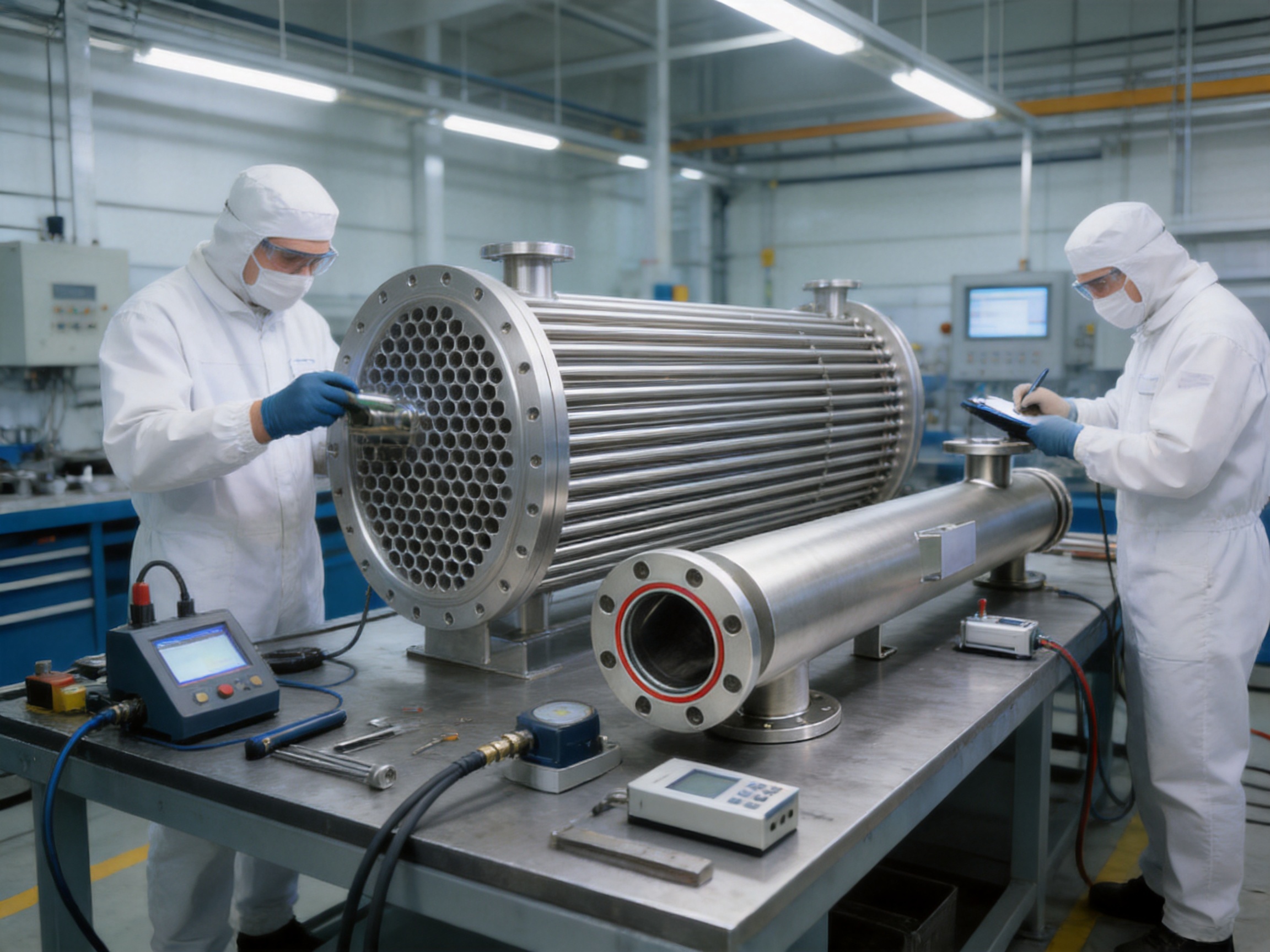
Sanitary equipment quality cannot be assessed by appearance alone. The external surface may look polished while internal tube connections, drainage paths, welds, or pressure boundaries require further verification. The reference inspection program therefore includes pressure testing, drainability testing, surface measurement, visual inspection, endoscopic inspection, internal cleaning, and documentation checks.
Pressure Retention Testing
Hydrostatic testing is used to verify the pressure retention performance and structural stability of the equipment. The test pressure, medium, duration, and acceptance criteria should be established according to the applicable design code, customer specification, and equipment category.
Pressure testing helps identify leaks, weak joints, deformation, or other pressure-boundary concerns before shipment. It should be supported by calibrated test instruments and documented test records. The final test package may include pressure charts, certificates, inspection signatures, and a statement of the test conditions.
Leak and Internal Structure Examination
The supplied material refers to fuel permeation testing with X-ray analysis as part of the pre-shipment inspection process. The precise test terminology and application should be confirmed for each project because inspection methods depend on the equipment design, material, service, and customer quality plan. Non-destructive examination may be used to check weld integrity, internal structure, or possible leakage paths.
For critical equipment, the inspection plan can be developed before fabrication. This allows the customer and supplier to agree on examination methods, inspection extent, acceptance criteria, and reporting format. Such planning is preferable to deciding inspection requirements after manufacturing has already begun.
Surface and Endoscopic Inspection
A surface profilometer can verify polished and electropolished areas. The reference requirement identifies an Ra value below 0.25 micrometers for designated surfaces. Endoscopic inspection is used to examine internal areas that cannot be evaluated directly by visual access, including tube interiors, bends, weld transitions, and other restricted locations.
Visual inspection and endoscopic inspection can identify discoloration, foreign material, surface damage, weld irregularities, residual debris, or geometry concerns. These inspections are particularly useful after polishing, cleaning, and internal blowout procedures.
Internal Cleaning and Blowout Inspection
Before packing, an internal blowout inspection is performed to verify that the inside of the equipment is free of debris. This step is important because machining particles, polishing residue, packaging material, or other foreign matter can remain hidden in tubes and internal passages if cleaning is not controlled.
The cleaning method should be compatible with the material and intended service. Depending on the project, it may include rinsing, controlled detergent cleaning, passivation, drying, filtered air or gas blowout, and visual or endoscopic confirmation. The final procedure must be defined according to the customer’s validation requirements.
Documentation and Validation Support
Documentation is a major part of sanitary equipment delivery. A complete package may include material certificates, welding records, welder qualifications, inspection reports, pressure test records, surface roughness results, dimensional inspection records, drainability results, calibration certificates, cleaning records, nameplate information, and final drawings.
The supplier’s validation document completeness check helps confirm that the agreed records are present before shipment. This reduces delays during site acceptance, commissioning, qualification, and internal quality review.
Compliance with Recognized Standards
The equipment is designed with reference to standards and regulatory frameworks including ASME BPE, TEMA recommendations, ASME pressure equipment requirements, Canadian Registration Number requirements where applicable, and CE/PED requirements for relevant European projects.
ASME BPE provides guidance for bioprocessing equipment, including hygienic design, materials, surface finishes, fabrication, inspection, and documentation. TEMA recommendations are widely used in the design and construction of shell-and-tube heat exchangers, including considerations related to thermal performance, mechanical integrity, vibration, and fouling.
CE/PED compliance may be required when the equipment is placed on the European market and falls within the scope of the Pressure Equipment Directive. Canadian projects may require CRN registration depending on the jurisdiction and equipment classification. The applicable requirements must be determined from the final design pressure, volume, fluid group, location of installation, and local regulations.
Standards should not be treated as interchangeable labels. Each project should identify which code or standard applies to the pressure boundary, hygienic design, surface finish, welding, inspection, documentation, and certification. The customer should also confirm whether additional regional, corporate, or process-specific requirements apply.
Reference Models and Dimensional Options
The following reference models illustrate how the number of U-tubes, tube diameter, shell diameter, total length, and weight may vary. These values are intended for preliminary comparison. Final dimensions must be confirmed through approved drawings and process calculations.
| Model | Number of U-tubes | U-tube diameter | Shell diameter | Total length | Reference weight |
| HY-SD-09065 | 9 | 10 mm | 90 mm | 1,050 mm | 56 kg |
| HY-SD-11065 | 11 | 10 mm | 102 mm | 1,050 mm | 75 kg |
| HY-SD-19150 | 19 | 10 mm | 116 mm | 1,900 mm | 90 kg |
| HY-SD-21150 | 21 | 10 mm | 140 mm | 1,900 mm | 115 kg |
The model information demonstrates the flexibility of the equipment family. Increasing the number of tubes can provide additional heat transfer capacity, but it also affects pressure drop, shell diameter, flow distribution, weight, support requirements, and cleaning conditions. A larger unit is not automatically a better unit. The appropriate selection must balance thermal duty, hygienic performance, installation constraints, and lifecycle cost.
Advantages Compared with Conventional Heat Exchangers
Improved Contamination Control
The most important advantage over a conventional single-tube-sheet exchanger is the additional barrier between the product and utility circuits. This feature is valuable when even a small probability of cross-contamination is unacceptable.
Better Leak Detection Potential
The intermediate zone between the tube sheets can act as a designated leak detection point. This creates an opportunity for early warning and planned maintenance instead of relying only on changes in product quality or downstream testing.
Greater Hygienic Adaptability
Drainable construction, controlled surface finish, sanitary connections, stainless steel materials, and inspection access make the unit better suited to hygienic processing than a general industrial heat exchanger.
Reduced Dependence on Expansion Joints
The U-tube design accommodates thermal expansion without a separate expansion joint in the referenced configuration. This can simplify the mechanical arrangement and reduce the number of components that require maintenance.
More Transparent Thermal Calculations
Calculating the heat transfer area using only the straight tube sections provides a clear basis for performance evaluation. Customers can compare the stated area with the actual effective geometry without relying on ambiguous inclusion of U-bend surfaces.
Greater Customization
Standard heat exchangers may not fit the piping arrangement, available space, process duty, or connection standard of every plant. The sanitary DTS design can be customized in tube diameter, tube count, heat transfer area, orientation, connections, supports, and other engineering parameters.
More Complete Project Support
A supplier with manufacturing, engineering, quality control, and international trade capabilities can support more than the physical equipment. Technical communication, documentation, inspection coordination, packing, export arrangements, and after-sales service can be managed as part of a more complete procurement solution.
Customization for Different Process Requirements
Customization begins with a complete process data sheet. Important information includes the product or process fluid, utility fluid, flow rates, inlet and outlet temperatures, operating and design pressures, maximum and minimum temperatures, cleaning chemicals, sterilization method, required surface finish, connection standard, installation orientation, and available space.
The product fluid is especially important. A low-viscosity water-based stream behaves differently from a concentrated syrup, protein solution, culture medium, oil, or suspension. Viscosity affects pressure drop and heat transfer. Solids or fibers may influence tube diameter and cleanability. Product sensitivity may limit the permissible wall temperature or residence time.
The utility side must also be defined. Cooling water, chilled water, glycol solution, hot water, steam, and other utilities have different heat transfer characteristics and pressure requirements. The selection should consider the utility’s cleanliness and the potential consequences of a leak into the product side.
Installation conditions can determine whether a horizontal or vertical unit is preferred. The engineering team should review the direction of flow, drain points, vent points, maintenance clearance, lifting access, support loads, piping flexibility, and the location of leak detection outlets. Factory-welded brackets can simplify installation, but the customer’s support structure must still be designed for the final equipment weight and operating loads.
Other customizable elements may include:
Tube outer diameter and wall thickness.
Number of U-tubes and total heat transfer area.
Shell diameter and overall length.
Product-side and utility-side connection sizes.
Tri-Clamp, flange, or project-specific connection arrangements.
Drain and vent locations.
Mounting brackets and lifting features.
Polishing and electropolishing requirements.
Instrumentation interfaces and leak detection provisions.
Material certificates and documentation format.
Pressure, temperature, and inspection standards required by the destination market.
Customization is most effective when it occurs before final design approval. Early technical communication can prevent later changes to piping, support structures, process control logic, or qualification documents.
Applications in Food, Beverage, and Biopharmaceutical Production
Injection Water and Purified Water Systems
The equipment is designed as a water intake cooler for injection water and purified water systems. These systems require careful control of temperature, drainability, surface quality, and contamination risk. The double tube sheet is particularly relevant where the utility medium must be separated from a high-purity water stream.
Biopharmaceutical Processing
Biopharmaceutical processes often involve high-value fluids and strict hygiene requirements. Heat exchangers may be used for process water, buffer preparation, media preparation, intermediate cooling, temperature adjustment, and other controlled operations. The appropriate configuration depends on whether the equipment is part of a sterile boundary, a cleanable process system, or a supporting utility system.
Food and Beverage Processing
Food and beverage operations may use sanitary heat exchangers for water cooling, syrup temperature control, beverage processing, dairy applications, liquid food products, and cleaning systems. The equipment must be compatible with frequent cleaning cycles and the particular viscosity, acidity, sugar content, or solids content of the product.
Daily Chemical and Fine Chemical Production
Although not every daily chemical or fine chemical process requires the same level of hygienic design as a biopharmaceutical process, many products benefit from cleanable stainless steel equipment and reliable media separation. The DTS configuration can be selected when product purity, batch consistency, and protection from utility contamination are important.
How to Select the Correct Sanitary DTS Heat Exchanger
Selection should begin with the heat duty rather than the model number. The heat duty is determined from the mass flow rate, specific heat, and required temperature change of the process fluid. The utility flow rate and temperature range then determine how much thermal driving force is available.
The following questions should be answered during selection:
What are the product-side and utility-side fluids?
What are the normal, minimum, and maximum flow rates?
What are the inlet and outlet temperatures?
What are the operating and design pressures?
What is the required heat load and acceptable temperature approach?
What pressure drop is permitted on each side?
Are there viscosity changes, suspended particles, or fouling risks?
What cleaning-in-place and sterilization procedures will be used?
Is complete drainage required in a specific orientation?
What surface roughness and material certificates are required?
Which standards and local certifications apply?
What are the available installation space and maintenance clearances?
Will the equipment be installed vertically or horizontally?
How will a possible double-tube-sheet leak be detected and documented?
The final design report should identify the selected heat transfer area, tube count, tube diameter, flow arrangement, pressure drop, heat transfer coefficient, fouling factors, design margins, mechanical design conditions, vibration results, and connection details.
Vibration, Resonance, and Mechanical Analysis
Flow-induced vibration can damage tubes, supports, baffles, and tube-to-tube-sheet joints if it is not evaluated during design. The risk depends on flow velocity, fluid density, tube span, tube stiffness, baffle spacing, turbulence, and the possibility of acoustic or mechanical resonance.
The design approach described in the supplied material includes 100 percent vibration and resonance analysis. This means that the analysis is applied to each applicable design rather than only to a limited sample of products. The purpose is to identify potentially harmful excitation conditions and optimize the internal structure accordingly.
Pressure points for tube and shell walls are also included in design reports based on customer-approved locations. This provides a more precise understanding of the mechanical load distribution. For multi-pass heat exchangers, whether using straight tubes or U-tubes, counter-current and cross-flow conditions are analyzed to support the thermal and hydraulic design.
Such analysis is especially important when the equipment operates at high flow rates, with large temperature differences, or under frequent cycling. A heat exchanger that performs well on paper but experiences vibration-related fatigue may create unplanned maintenance and contamination risks. Mechanical analysis is therefore directly connected to hygienic reliability.
Installation, Commissioning, and Maintenance Considerations
The equipment should be installed according to the approved general arrangement drawing and piping design. Supports must accommodate the operating weight, test weight, thermal movement, and connected-pipe loads. Lifting brackets should be used according to their rated capacity and the supplier’s handling instructions.
Before commissioning, the customer should verify that the product and utility connections correspond to the approved flow diagram. The drain and vent lines should be routed so that the equipment can be fully drained and safely vented. Instrumentation and leak detection points should be connected to the plant monitoring system where required.
Initial commissioning may include flushing, pressure testing of the connected piping, confirmation of valve orientation, verification of flow direction, and inspection for external leakage. The first operating cycle should be monitored for pressure drop, outlet temperature, vibration, unusual noise, and evidence of leakage at the double tube-sheet detection points.
Maintenance procedures should be based on the process risk assessment. Routine checks may include external inspection, connection inspection, drain verification, surface condition review, pressure trend analysis, and confirmation that the leak detection area remains unobstructed. If the process experiences frequent fouling, the cleaning schedule should be adjusted according to actual performance data.
When opening the equipment, hygienic practices should be followed to protect internal surfaces. Replacement gaskets and components should meet the approved material and dimensional requirements. Any repair affecting the pressure boundary, tube joints, polished surfaces, or double-tube-sheet region should be documented and evaluated before the unit returns to service.
Why Supplier Capability Matters
Purchasing a sanitary DTS heat exchanger from an experienced supplier can reduce technical and commercial risks. A specialized supplier understands that the equipment is part of a larger process system, not an isolated commodity. The supplier should be able to interpret process data, recommend a suitable configuration, prepare drawings and calculations, coordinate inspections, and support documentation requirements.
The company described in the supplied information focuses on international trade, import and export agency services, equipment manufacturing, and engineering and technical support. This is useful for overseas customers who may need assistance with quotation comparison, technical clarification, export packing, shipping coordination, and communication between the end user, engineering contractor, and equipment manufacturer.
The company’s stated capabilities in processing, welding, polishing, and quality control support an integrated manufacturing model. Internal coordination among these functions can improve consistency and reduce the possibility that design intent will be lost during production.
The company also emphasizes traceability, safe and efficient equipment, reliable supply, process optimization, and personalized customer service. These capabilities are particularly valuable in projects where the customer requires a complete technical file, customized interfaces, or coordination with an international validation and quality team.
Economic Value and Lifecycle Benefits
The initial purchase price is only one part of the cost of a heat exchanger. A more meaningful comparison should include energy consumption, cleaning time, maintenance frequency, downtime risk, qualification effort, replacement costs, and the consequences of product contamination.
The sanitary DTS design can create lifecycle value in several ways. Early leak detection may reduce the duration and scope of an incident. Full drainability can reduce residual product and shorten cleaning or changeover operations. The expansion joint-free U-tube configuration can reduce the number of separate components requiring maintenance. Efficient hydraulic design can limit pumping energy while preserving thermal performance.
These benefits should be evaluated with realistic operating data. For example, a design with a lower purchase price but a higher pressure drop may increase pump energy throughout its service life. A unit that cannot drain effectively may create repeated cleaning delays. An exchanger without adequate documentation may generate additional qualification costs for a regulated facility.
A properly selected sanitary DTS heat exchanger is therefore an investment in production continuity, product protection, compliance support, and predictable maintenance. The exact return depends on the process and should be confirmed through a project-specific lifecycle assessment.
Frequently Asked Questions
Q1: What is the main purpose of a double tube sheet?
A: The double tube sheet creates an additional physical separation barrier between the product and utility circuits. The intermediate region can serve as a leak detection area, helping identify a tube or connection problem before direct cross-contamination occurs.
Q2: Is a sanitary DTS heat exchanger suitable for purified water and injection water systems?
A: Yes. The referenced design is intended for water intake cooling applications involving purified water and injection water systems. Final suitability depends on the required temperature, pressure, flow rate, surface finish, drainage, material, cleaning, and validation requirements.
Q3: Can the unit be installed horizontally?
A: Yes. The unit can be designed for horizontal or vertical installation. The preferred orientation depends on available space, drainage, venting, maintenance access, process piping, and the customer’s equipment layout.
Q4: What materials are available?
A: Reference material options include 304 stainless steel, 316L stainless steel, and project-specific material configurations. Imported SUS316L tubes are identified for the sanitary heat exchange tube bundle. The final material selection should consider the process fluid, cleaning chemistry, sterilization conditions, and applicable standards.
Q5: What surface roughness can be provided?
A: The reference specification includes surface finish options from approximately Ra 0.25 micrometers to Ra 0.8 micrometers, depending on the application. Specific polished areas may be controlled below Ra 0.25 micrometers. The exact value should be stated in the approved technical specification and verified by measurement.
Q6: Does the heat transfer area include the U-bends?
A: No. The referenced calculation method counts only the straight tube sections. The U-bends are excluded from the stated heat transfer area, providing a transparent and conservative basis for capacity evaluation.
Q7: Why is the U-tube design useful?
A: The U-tube geometry accommodates thermal expansion and can reduce the need for a separate expansion joint. It also supports compact construction. Accurate bending, controlled radii, and proper inspection are required to ensure reliable performance.
Q8: How is the tube-to-baffle connection made?
A: The referenced manufacturing process uses hydraulic expansion to join tubes and baffles. This process can reduce surface damage and improve consistency compared with conventional roller expansion when correctly controlled.
Q9: Can the tube diameter and heat transfer area be customized?
A: Yes. Tube diameter, tube count, heat transfer area, shell dimensions, connection configuration, installation orientation, mounting features, and other parameters can be customized according to the process and site requirements.
Q10: What tests are performed before shipment?
A: The reference inspection program includes hydrostatic pressure testing, drainability testing, surface roughness measurement, visual inspection, endoscopic inspection, internal blowout inspection, documentation review, and computer-based performance verification. Additional non-destructive examinations or customer-specific tests may be included in the inspection and test plan.
Q11: Which standards may apply?
A: The supplied specifications reference ASME BPE, TEMA recommendations, ASME pressure equipment requirements, CRN, and CE/PED. The applicable standards depend on the project location, equipment classification, pressure and temperature conditions, and customer requirements.
Q12: What information is needed for a quotation?
A: A quotation normally requires product and utility fluid information, flow rates, inlet and outlet temperatures, operating and design pressures, cleaning and sterilization conditions, required surface finish, connection standards, installation orientation, available space, applicable certifications, and documentation requirements.
Q13: How does the supplier support overseas projects?
A: In addition to equipment manufacturing and engineering support, the supplier can assist with international trade coordination, import and export agency services, technical communication, inspection documentation, packing, and shipment arrangements. The exact scope should be agreed during the project quotation stage.
Conclusion
The sanitary DTS heat exchanger is designed for applications where heat transfer performance must be combined with strict control of contamination risk. Its double tube sheet structure creates a stronger separation concept than a conventional single-tube-sheet arrangement and provides designated points for leak detection. Full-drain construction, sanitary connections, 316L stainless steel tubes, controlled surface finish, U-tube expansion management, and comprehensive inspection further support hygienic operation.
Its value is also connected to the manufacturing process behind the equipment. Hydraulic tube expansion, accurate U-bend fabrication, forged thickened double plates, surface polishing, pressure testing, endoscopic inspection, drainability verification, and documentation control all contribute to reliable service. Engineering tools, heat transfer databases, vibration analysis, fouling calculations, and transparent design reports help ensure that the selected unit matches the customer’s process rather than simply fitting a standard product category.
For food and beverage manufacturers, biopharmaceutical companies, purified water projects, and other high-hygiene facilities, the correct heat exchanger can influence product safety, production continuity, energy use, maintenance planning, and regulatory readiness. A customized sanitary DTS unit offers a practical approach for companies that require both thermal efficiency and a more robust safety barrier between process media.
With manufacturing, engineering, quality control, international trade, and supply chain coordination capabilities, Shiloc (Shanghai) Industrial Trading Co., Ltd. provides customized sanitary heat exchange solutions for customers seeking reliable equipment for domestic and global projects. The final design should always be confirmed through an approved technical specification, process calculation, mechanical review, inspection plan, and applicable certification strategy.
References
1. ASME BPE, Bioprocessing Equipment Standard, American Society of Mechanical Engineers.
2. TEMA Standards, Standards of the Tubular Exchanger Manufacturers Association.
3. Pressure Equipment Directive 2014/68/EU, European Union.
4. ASME Boiler and Pressure Vessel Code, applicable pressure vessel and pressure equipment sections.
5. Current Good Manufacturing Practice requirements for pharmaceutical and biopharmaceutical manufacturing facilities.
6. United States Food and Drug Administration guidance concerning sanitary processing and pharmaceutical manufacturing controls.
7. Hygienic design principles for food, beverage, pharmaceutical, and bioprocess equipment.
8. Manufacturer technical specifications for sanitary double tube sheet heat exchangers, including reference dimensions, materials, testing, and surface finish requirements.
Product: Sanitary DTS (Double Tube Sheet) Heat Exchanger
PREV:Ultra-High Temperature Tube Pasteurizer for Food, Beverage, and Biopharmaceutical Processing
NEXT:No next article
NEXT:No next article
Interested in cooperation or have questions?
Recommended LINS
✦
Food Processing Skid System
Food and Beverage Process System
Sanitary Process Skid
CIP Skid System for Food Industry
food and beverage process skid system
hygienic process skid for food industry
CIP process skid system for food industry
automated process skid system for food processing
sanitary process skid system
modular food processing skid system
Let'S Work Together Welcome Aboard!
-

haikexin@haikexin.com
+8613391278930
-
 +86-21-57560276
 -
 No. 2819, Sihu Road,Fengxian District, Shanghai, China
Join Our Mailing List
Copyright © Shiloc (Shanghai) Industrial Trading Co., Ltd. All Rights Reserved.
Process Systems & Equipment For Food & Biopharma Manufacturers
